


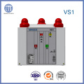
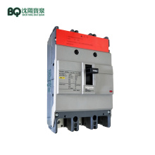
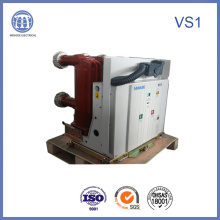
12kv Vs1 Indoor High-Voltage Vacuum Circuit Breaker with Embedded Pole
Basic Info
Model No.: VS1
Product Description
Model NO.: VS1 Operation: Manual and Electric Type Breaker Arc-extinguishing Medium: Vacuum Structure: Vcb Breaker Type: Circuit Breaker Certification: ISO9001-2000, CCC, Ohsas 180001 Rated Current: 630/1250/1600/2000A Circuit Breaker Rated Frenquency: 50 Hz Circuit Breaker Rated Peak Withstand Current: 50/63/80/100 Ka Circuit Breaker Transport Package: Plywood for Circuit Breaker Origin: Zhejiang Ningbo Circuit Breaker Breaking Capacity: High and Medium Voltage Circuit Breaker Speed: Normal Type Circuit Breaker Installation: Fixed and Handcart Type Breaker Poles Number: 3 Function: Overcurrent Protection Rated Voltage: 12kv Circuit Breaker Rated Short - Circuit Opening Current: 20/25/31.5/40ka Circuit Breaker Rated Short-Time Withstand Current: 20/25/31.5/40 Ka Circuit Breaker Trademark: Mingde Circuit Breaker Specification: SGS, TUV HS Code: 8535210000 12kV VS1 Indoor High-Voltage Vacuum Circuit Breaker with Embedded Pole

1 Overview VS1(ZN63A) series vacuum breaker is of indoor High Voltage Switchgear suitable for 12kV. Threephase power system with 50Hz frequency in order to protect and control electrical appliances, and especially suitable for frequent operation at rated current or incessant open circuit due to unique advantages of Vacuum Circuit Breaker.
Spring operating mechanism and breaker body parts adopt integration design. Thank for this design, breaker not only can be a fixed installation unit, but also can be a withdrawable unit with a specially pushing framework. For meet the requirement of XGN2, GG1A cabinet, the fixed type breaker can be install additionally interlock.
2. Product reference standard
Shall be in accordance with standards in GB198489 Alternating Current High
Voltage Breaker, JB38551996 3.6~40.5kV Indoor Alternating Current High Voltage Vacuum Breaker, and DL4031999 Specification for Order of 10~35kV Indoor High Voltage Vacuum Breaker, and subject to relative requirements in IEC56 (87 publication).
3 Operating environment condition
A) Normal operating environment condition
Highest temperature: +40ºC
Lowest temperature: -15ºC
B) Environment humidity
Daily mean relative humidity: ≤95%
Monthly mean relative humidity: ≤90%
Daily mean saturated vapor pressure: ≤2.2×10⁻³ MPa
Monthly mean saturated vapor pressure: ≤1.8×10⁻³ MPa
C) Altitude: Below 1000m area;
D) Earthquake intensity: No more than 8 degree;
E) The product shall be away from weep, fire and explosion, chemical corrosion and strenuous vibration place.
4. Main specifications and technical parameters
5 Product structure and operating principle
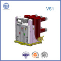
5.1 Body structure
Spring operating mechanism and main parts adopt integration desigh, primary
Conductive circuit install in tube located in the rear of breaker and the mechanism is
In the front of breaker, which the tube is apopt epoxy resin as material and used
Advanced APG technology for forming. Thank to this material, vacuum interrupter
Can avoid harmful effect from external factor.
Primary conductive circuit current route of breaker at closing position as follow: (refer to Pic 2): Current flows from upper outlet holder 27 through upper support 26
Fixed on the upper part of arc extinguish chamber to fixed contact in the vacuum
Interrupter, then through moving contact and conductor clasp, flexible joint to
Lower support 30, to lower outlet holder 31 into a complete conductance circuit.
While being delivered from the factory, Proofdust insulating tube cover is install on all current level 's breaker. While start to use, it is not necessary to remove while the current is equal to 1250A or less than 1250A, but it must be remove, if the current up to 1600A or pass 1600A.
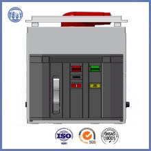
5.2 Operating mechanism(refer to Pic 1, Pic 2)
Operating mechanism is in the form of spring storage energy. It including closing cell, opening cell (composed of one or some trip coil), aux switch, indicator device and
So on. In the front of it, there are closing/opening button, manual storage energy operatin hole, indicator of storage-energy situation, indicator of closing/opening
And so on.
5.2. 1 Stored energy operation
While start to closing, the need power is come from closing spring's stored-energy activity. This activity not only can be finished by motor, but also can
Be used manual operating by handle Stored energy operation: Used motor 16 for
Stored or manual operating by anticlockwise wing handle. If use motor stored, the sprocket transmission system(14, 23, 18) is driven by Motor outputshaf 15, if use manual operating, the sprocket transmission system(14, 23, 18) is driven by worm(11, 13).
While the sprocket rotating, pin 2 push the slide4 fixed on wheel 6 move so that let stored energy shaft 7 rotate, so as to execute stored energy through stretching closing spring via crank(5, 21). While reach stored energy position, the limited rod3 press slide 4so as to separate stored energy shaft from sprocket transmission system, stored
Energy retaining stand 9 prop roll wheel 8 for keep stored energy position.
Meanwhile connection plate 24 fixed on stored energy shaft driving indicator show
"Already stored " and switchover aux switch for cut motor's power supply, after it,
The breaker is in closing preparation state.
5.2. 2 Closing operation
While clsoing operaitng, the closing coil can be move by press "closing"button or remote manipulation, this activity can driving stored energy retaining shaft 19 rotate,
And as so to retaining stand 9 release roll wheel 8. Closing spring shrink and through
Crank (5, 21) driving stored energy shaft 7 and cam 22 fixed on shaft rotate, cam's
Rotate movement driving connection rod mechanism(34, 36, 37, 38, 39) to drive
Insulating pull rod 33 and move contact entry into closing position, and compress disc spring 32, for keep the contact pressure of contact wanted. After closing activity finished, closing retaining stand 38 and semiaxis keep in closing position, meanwhile store energy indicator and stored energy aux switch recovery motor's supply circuit
Connecting. It will be entry storedenergy state again, if external power source
Connecting, and connection plate 44 driving closing/opening indicator and show
"Closing", main aux switch switchover by transmission connection rod pulling.
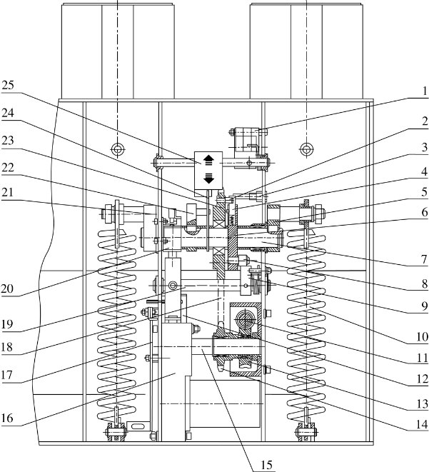
Pic
1Micro switch using switching while Stored energy finished 2 Pin 3 Limited rod
4 Slide 5 Crank 6 Stored energy transmission wheel 7 Stored energy shaft
8 Roll wheel 9 Stored energy retaining stand 10 Clsoing spring
11 Manual Stored energy worm 12 Closing electromagnet
13 manual Stored energy transmission worm 14 Motor transmission sprocket
15 Motor outputshaft 16 Motor 17 Interlock transmission bending plate
18 transmission sprocket 19 Stored energy retaining shaft 20 Lock electromagnet
21 Crank 22Cam 23 Stored energy transmission sprocket 24 Connection plate
25 indicator
5.2. 3 Opening operation
This activity can be realize by press "Opening" button, or connect external power
Source to drving opening trip coil or overcurrent trip coil as so to unlock closing
Retaining stand 38 from semiaxis 41 for reach to opening. The contact spring and
Energy of opening spring 35 driving vacuum interrupter 28 's fixed and move contact separate. In the rear stage of openning process, the hydrolic will absorb the leaving energy and limit the separate position. Connection plate 44 driving closing/opening indicator and show"Opening", meanwhile counter implements counting, main aux switch Switchover by transmission connection rod pulling.
5.3 Fool proof interlock
VS1 series vacuum breaker offers complete function for fool proof operation
(Refer to Pic 3 and Pic 4)
1. After closing operating finished, closing interlock bend plate 1 downward moving
To buckle closing bend plate 2, the breaker can not closing again before opening.
2. After closing finished, If the closing electrical sign not remove in time, inner anti-pumping control circuit will cut off closing circuit for avoid reclose. (Optional)
3. Before handcart type breaker reach to working position or testing position, the
Interlock's bended plate 3 will buckle pin 4 fixed on closing bended plate 2, and
Cut off the circuit of closing, avoid breaker entry loading area in closing state.
4. After handcart type breaker clsoing in working position or testing position, roll
Wheel 5 press pushing framework 's locking plate 6, the truck can not move any more,
For avoid push in or push out loading area in closing state. (Refer to Pic 4)
5. If adopt to electric closing lock, the clsoing operating is not allowed while not use
Lock device to unlock
Remark: The power of closing lock device is 2.7W, the normal voltage scope is
65%~110% of rated voltage
Production Process
 Contact us if you need more details on Circuit Breaker. We are ready to answer your questions on packaging, logistics, certification or any Other aspects about Breaker、Vacuum Interrupter. If these products fail to match your need, please contact us and we would like to provide relevant information.

1 Overview VS1(ZN63A) series vacuum breaker is of indoor High Voltage Switchgear suitable for 12kV. Threephase power system with 50Hz frequency in order to protect and control electrical appliances, and especially suitable for frequent operation at rated current or incessant open circuit due to unique advantages of Vacuum Circuit Breaker.
Spring operating mechanism and breaker body parts adopt integration design. Thank for this design, breaker not only can be a fixed installation unit, but also can be a withdrawable unit with a specially pushing framework. For meet the requirement of XGN2, GG1A cabinet, the fixed type breaker can be install additionally interlock.
2. Product reference standard
Shall be in accordance with standards in GB198489 Alternating Current High
Voltage Breaker, JB38551996 3.6~40.5kV Indoor Alternating Current High Voltage Vacuum Breaker, and DL4031999 Specification for Order of 10~35kV Indoor High Voltage Vacuum Breaker, and subject to relative requirements in IEC56 (87 publication).
3 Operating environment condition
A) Normal operating environment condition
Highest temperature: +40ºC
Lowest temperature: -15ºC
B) Environment humidity
Daily mean relative humidity: ≤95%
Monthly mean relative humidity: ≤90%
Daily mean saturated vapor pressure: ≤2.2×10⁻³ MPa
Monthly mean saturated vapor pressure: ≤1.8×10⁻³ MPa
C) Altitude: Below 1000m area;
D) Earthquake intensity: No more than 8 degree;
E) The product shall be away from weep, fire and explosion, chemical corrosion and strenuous vibration place.
4. Main specifications and technical parameters
| NO | Item | Unit | Technical Data |
| 1 | Rated voltage | KV | 12 |
| 2 | 1 min power frequency withstand voltage | 42 | |
| Lighting impulse withstand voltage(peak value) | 75 | ||
| 3 | Rated Frequency | Hz | 50 |
| 4 | Rated current | A | 630, 1250, 1600, 2000, 2500, 3150, 4000 |
| 5 | Rated short time withstand current | KA | 20, 25, 31.5, 40 |
| 6 | Rated withstand current(peak) | 50, 63, 80, 100 | |
| 7 | Rated short-circuit opening current | 20, 25, 31.5, 420 | |
| 8 | Rated short-circuit closing current | 50, 63, 80, 100 | |
| 9 | Rated duration of short-circuit | S | 4 |
| 10 | Contact's clearance | 3.5±0.5 | |
| 11 | Contact's travel | 9±1/11±1 | |
| 12 | Average opening speed | M/s | 1.1±0.2 |
| 13 | Average closing speed | M/s | 0.6±0.2 |
| 14 | Opening time | Ms | 35-60 |
| 15 | Closing time | Ms | 20-45 |
| 16 | Mechanical life | Times | 30000 |
| 17 | Rated operating order | O-0.3S-CO-180S-CO(<40KA) O-180S-CO-180S-CO(≥40KA) |
5 Product structure and operating principle
5.1 Body structure
Spring operating mechanism and main parts adopt integration desigh, primary
Conductive circuit install in tube located in the rear of breaker and the mechanism is
In the front of breaker, which the tube is apopt epoxy resin as material and used
Advanced APG technology for forming. Thank to this material, vacuum interrupter
Can avoid harmful effect from external factor.
Primary conductive circuit current route of breaker at closing position as follow: (refer to Pic 2): Current flows from upper outlet holder 27 through upper support 26
Fixed on the upper part of arc extinguish chamber to fixed contact in the vacuum
Interrupter, then through moving contact and conductor clasp, flexible joint to
Lower support 30, to lower outlet holder 31 into a complete conductance circuit.
While being delivered from the factory, Proofdust insulating tube cover is install on all current level 's breaker. While start to use, it is not necessary to remove while the current is equal to 1250A or less than 1250A, but it must be remove, if the current up to 1600A or pass 1600A.
5.2 Operating mechanism(refer to Pic 1, Pic 2)
Operating mechanism is in the form of spring storage energy. It including closing cell, opening cell (composed of one or some trip coil), aux switch, indicator device and
So on. In the front of it, there are closing/opening button, manual storage energy operatin hole, indicator of storage-energy situation, indicator of closing/opening
And so on.
5.2. 1 Stored energy operation
While start to closing, the need power is come from closing spring's stored-energy activity. This activity not only can be finished by motor, but also can
Be used manual operating by handle Stored energy operation: Used motor 16 for
Stored or manual operating by anticlockwise wing handle. If use motor stored, the sprocket transmission system(14, 23, 18) is driven by Motor outputshaf 15, if use manual operating, the sprocket transmission system(14, 23, 18) is driven by worm(11, 13).
While the sprocket rotating, pin 2 push the slide4 fixed on wheel 6 move so that let stored energy shaft 7 rotate, so as to execute stored energy through stretching closing spring via crank(5, 21). While reach stored energy position, the limited rod3 press slide 4so as to separate stored energy shaft from sprocket transmission system, stored
Energy retaining stand 9 prop roll wheel 8 for keep stored energy position.
Meanwhile connection plate 24 fixed on stored energy shaft driving indicator show
"Already stored " and switchover aux switch for cut motor's power supply, after it,
The breaker is in closing preparation state.
5.2. 2 Closing operation
While clsoing operaitng, the closing coil can be move by press "closing"button or remote manipulation, this activity can driving stored energy retaining shaft 19 rotate,
And as so to retaining stand 9 release roll wheel 8. Closing spring shrink and through
Crank (5, 21) driving stored energy shaft 7 and cam 22 fixed on shaft rotate, cam's
Rotate movement driving connection rod mechanism(34, 36, 37, 38, 39) to drive
Insulating pull rod 33 and move contact entry into closing position, and compress disc spring 32, for keep the contact pressure of contact wanted. After closing activity finished, closing retaining stand 38 and semiaxis keep in closing position, meanwhile store energy indicator and stored energy aux switch recovery motor's supply circuit
Connecting. It will be entry storedenergy state again, if external power source
Connecting, and connection plate 44 driving closing/opening indicator and show
"Closing", main aux switch switchover by transmission connection rod pulling.

Pic
1Micro switch using switching while Stored energy finished 2 Pin 3 Limited rod
4 Slide 5 Crank 6 Stored energy transmission wheel 7 Stored energy shaft
8 Roll wheel 9 Stored energy retaining stand 10 Clsoing spring
11 Manual Stored energy worm 12 Closing electromagnet
13 manual Stored energy transmission worm 14 Motor transmission sprocket
15 Motor outputshaft 16 Motor 17 Interlock transmission bending plate
18 transmission sprocket 19 Stored energy retaining shaft 20 Lock electromagnet
21 Crank 22Cam 23 Stored energy transmission sprocket 24 Connection plate
25 indicator
5.2. 3 Opening operation
This activity can be realize by press "Opening" button, or connect external power
Source to drving opening trip coil or overcurrent trip coil as so to unlock closing
Retaining stand 38 from semiaxis 41 for reach to opening. The contact spring and
Energy of opening spring 35 driving vacuum interrupter 28 's fixed and move contact separate. In the rear stage of openning process, the hydrolic will absorb the leaving energy and limit the separate position. Connection plate 44 driving closing/opening indicator and show"Opening", meanwhile counter implements counting, main aux switch Switchover by transmission connection rod pulling.
5.3 Fool proof interlock
VS1 series vacuum breaker offers complete function for fool proof operation
(Refer to Pic 3 and Pic 4)
1. After closing operating finished, closing interlock bend plate 1 downward moving
To buckle closing bend plate 2, the breaker can not closing again before opening.
2. After closing finished, If the closing electrical sign not remove in time, inner anti-pumping control circuit will cut off closing circuit for avoid reclose. (Optional)
3. Before handcart type breaker reach to working position or testing position, the
Interlock's bended plate 3 will buckle pin 4 fixed on closing bended plate 2, and
Cut off the circuit of closing, avoid breaker entry loading area in closing state.
4. After handcart type breaker clsoing in working position or testing position, roll
Wheel 5 press pushing framework 's locking plate 6, the truck can not move any more,
For avoid push in or push out loading area in closing state. (Refer to Pic 4)
5. If adopt to electric closing lock, the clsoing operating is not allowed while not use
Lock device to unlock
Remark: The power of closing lock device is 2.7W, the normal voltage scope is
65%~110% of rated voltage
Production Process
 Contact us if you need more details on Circuit Breaker. We are ready to answer your questions on packaging, logistics, certification or any Other aspects about Breaker、Vacuum Interrupter. If these products fail to match your need, please contact us and we would like to provide relevant information.
 Product Categories : Circuit Breaker
Premium Related Products

Other Products
Hot Products
Fuse Combination Unit Load Break Switch with Grounding Knife-Yfn5-12r (T) D/125-31.5Reasonble Price for Zinc-Oxide Lightning ArresterCkg Series High-Voltage Vacuum ContactorFn5-12r (T) D-Hv Load Switch with Reasonable Price.Hxgn-24 Indoor Ring Net Cabinet with High Quality, Reasonble PriceBest Selling, Reasonable Price&Good Service of Yfzn35-40.5 Series Vacuum Load Switch with FuseYFZRN-24 AC Hv Vacuum Load Switch with Safe and Easy Fuse12kv Series Factory Manufacture High-Voltage Isolating Switch--Yfg38-12D12kv Vacuum Arc Extinction High-Voltage Circuit Breaker Indoor Use -Vs1Fn5-12r (T) D Indoor AC Hv Load Switch-Fuse Combination UnitContact Box Md/150Mdgear 550 Solid Insulation Metal-Clad SwitchgearKyn61 Clad-Metal Drawable AC Metal Closed Switchgear550 Modularized Omni-Sealed Solid Insulation Metal-Clad Switchgear12kv Vs1 Indoor High-Voltage Vacuum Circuit Breaker with Embedded Pole12kv 630A Vmd Hv Electric Vacuum Breaker